
MultiTrace

Automated curve tracing for semiconductor reliability and device evaluation.
MultiTrace is a compact, benchtop curve tracer supporting up to 1152 pins. It runs on RTI’s DataTrace software, providing direct control of hardware, calibration, test setup, and data analysis. Designed for engineering and production environments, MultiTrace supports failure analysis, nondestructive electrical test, counterfeit detection, and both powered and unpowered curve tracing across a wide range of test configurations.
For users looking for the MT Century, it’s now part of the MultiTrace line. The same fixtures, configurations, and lower pin counts remain available. Contact us for details or compatibility support.
MultiTrace
Automated curve tracing for semiconductor reliability and device evaluation.
MultiTrace is a compact, benchtop curve tracer supporting up to 1152 pins. It runs on RTI’s DataTrace software, providing direct control of hardware, calibration, test setup, and data analysis. Designed for engineering and production environments, MultiTrace supports failure analysis, nondestructive electrical test, counterfeit detection, and both powered and unpowered curve tracing across a wide range of test configurations.
For users looking for the MT Century, it’s now part of the MultiTrace line. The same fixtures, configurations, and lower pin counts remain available. Contact us for details or compatibility support.
Overview

MultiTrace is RTI’s benchtop curve tracer system for electrical characterization, failure analysis, and counterfeit device detection. It provides non-destructive electrical test on integrated circuits, bare die, and board-level assemblies. Designed for lab environments that require flexibility and repeatable results, MultiTrace supports a wide range of package types and pin configurations while maintaining stable electrical performance across each test condition.
About MultiTrace
MultiTrace sources and measures current and voltage to capture signatures and identify device behavior under bias. It supports automated sweeps and comparison testing for analyzing opens, shorts, leakage, and functional response. MultiTrace systems connect directly to RTI sockets, DUT boards, and adapter fixtures, offering dependable contact integrity and easy reconfiguration between test setups.
Each system is shipped complete with a controller, LCD monitor, and DataTrace Basic software package for test setup, curve display, and data management. Optional software upgrades expand automation, analysis, and reporting capability for larger lab workflows.
Key Capabilities
- Perform powered and unpowered curve tracing across multiple device types
- Execute automated voltage and current sweeps with programmable parameters
- Compare device response to known-good references for anomaly detection
- Detect opens, shorts, and leakage through graphical I-V results
- Support latch-up, ESD, and reliability testing
- Interface with optical fault-localization tools and external analysis equipment
- Save, overlay, and export data for documentation and correlation
- Fully compatible with RTI sockets, DUT boards, and adapter fixtures
Hardware of MultiTrace

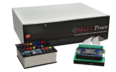
MultiTrace features a benchtop design, starting with a core system that includes a test chassis (pictured above) with a switch card and power supply. This foundational setup can be customized and expanded into various configurations to accommodate higher pin counts and enhance functionality.
Common Features:
- Benchtop Form fits on half of a typical lab bench
- 216, 324, 432 and 625 pin configurations are popular (other sizes available)
- Supports 2, 4, and 6 bus standard configurations
- 2 bus, 1080 pin with Octopogo interface available for Desktop MultiTrace
- Fixtures include access to all drives and measurement nodes by way of Banana Jacks
- Most Configurations are Upgradable
- Remote cable available for interface with microscope for Fault Localization Methods
Test Applications Supported
Failure Analysis: MultiTrace allows for detailed characterization of devices that have failed in production or in the field, identifying anomalies and clues that can lead to the root causes of failure in an effort to prevent future occurrences and improve product design.
Reliability Testing: With MultiTrace, devices undergo rigorous testing under various environmental and operational conditions can be monitored for damage to the electrical connection to the pins in order to ensure their long-term reliability and performance.
Counterfeit Device Analysis: MultiTrace is useful for verifying the authenticity of electronic components, protecting the supply chain from counterfeit parts that can compromise system integrity. Signatures of devices can be saved and compared among like devices to show similar internal construction.
Nondestructive Electrical Test: This application utilizes MultiTrace to perform electrical testing on suspected counterfeit devices without causing any physical damage, ensuring their functionality and compliance with specifications after testing is done.
Opens, Shorts, and Leakage Testing (OSL): MegaTrace provides precise measurements for detecting open circuits, short circuits, and leakage currents in electronic devices, crucial for quality control and troubleshooting. Evaluate linearity of leakage and shorts just by looking.
Post-Decap Electrical Inspection: After decapsulation of an integrated circuit, MultiTrace curve trace results can be compared to before decapsulation to show it has not changed as a result of the procedure.
Optical Fault Localization: Using advanced optical techniques, MultiTrace helps provide the necessary electrical bias to the leakage to aid in pinpointing the exact location of faults within a device, enabling efficient and accurate repairs.
ESD Testing: When Electrostatic Discharge (ESD) testing is done using other tester hardware, MultiTrace test results help find the damage that may have occured and helps ensure that devices can withstand electrostatic events, which are common in real-world environments, thereby preventing premature failures.
Latch-Up Testing: MultiTrace is one of the very few automated tools that conducts latch-up testing to assess the susceptibility of CMOS circuits to latch-up conditions, which can lead to catastrophic device failure if not properly managed.
Supply Current Measurements: By measuring the supply current accurately, MultiTrace helps in identifying excessive power consumption issues and ensuring that devices meet their power efficiency targets. High Static Supply Current (IDDQ) is a common failure signature that Multitrace can measure using repeatable, easy-to-configure test conditions.
Up to 108 Pins and Fixture Boards

The MultiTrace line offers flexible 96/100/108-pin options and reliable R1 and RSK fixture board types.

The MultiTrace 100 pin model, formerly known as “MT Century”, comprises a single test chassis with backplane. It comes complete with a single test cable and is available in optimized formats of 96 or 100 pins. R1 fixture types are the primary choice for this model, supporting packages and devices with pin counts from 96 to a maximum of 108.

R1 fixtures are designed to be flexible and seamlessly integrate with MultiTrace systems through a dedicated DUT board and a 100-pin connector.
Basic fixtures provide compatibility with adapters having DIP, and PGA footprints, while dedicated fixtures feature an RTI socket and lid. Open top and open bottom features make these a very flexible DUT board platform.
The R1 is versatile for a range of testing situations. With compatibility for all RTI 1.5-inch test sockets and most third-party sockets, R1 fixtures ensures precise and adaptable results in a user-friendly setting.
Compatibility with the RTI 950 Series Fixture and Mini-card DUT boards is available for the MultiTrace 100 models. You can get them in either 96 or 100-pin optimized formats. Furthermore, we also provide the 96-pin Double DIP-48 Fixture and the PGA-108 pin fixture, offering partial compatibility with PGA fixtures.
Up to 216-pins and Fixture Boards
Experience the power of our expanded MultiTrace configurations, offering efficient and reliable testing solutions with our 192/200/216-pin setups and versatile R2 and RSK fixture board types.

2 backplanes and 2 cable connectors.
The MultiTrace 200 model comprises a single test chassis with two backplanes, and two test cables. This configuration is ideal for devices that need up to 216 pins and is available in either 96 or 100-pin optimized formats.
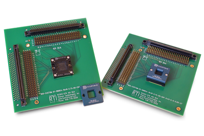
Devices with a slightly higher number of pins can benefit from the R2 fixture, which includes a DUT board equipped with two sturdy 96 or 100 channel, 100-pin connectors. With extensive connectivity options, these fixtures enable comprehensive testing procedures.
The R2 fixture incorporates unique standoffs that facilitate access to the backside of the DUT board and the base plate. With this design, you can efficiently test the backside without having to reconfigure anything, thanks to the ample clearance for sockets and cables.
With the R2 fixture, you can expect consistent performance and effortless operation, whether you’re performing routine quality checks or detailed component failure analysis. This tool is indispensable for any electronics testing lab, ensuring both accuracy and efficiency.
Up to 432-pins and Fixture Boards
Discover the wide range of features offered by our expanded MultiTrace configurations, available in different setups including 284/300/324-pin and 384/400/432-pin, with versatile R4 and RSK fixture board options.

Backside of 300 or 400 models with backplanes and cables.
With the MultiTrace 300 and 400 models, you get a package that comprises two test chassis and either three or four backplanes, each accompanied by its own set of test cables. Complete access to all 432 pins is available in either 96 or 100-pin optimized formats.


ADD: Image: need an R4 with only connectors on bottom, this is the default configuration
Designed to offer a wide range of connectivity and testing possibilities, the R4 fixture is equipped with a DUT board that features four active connectors. These connectors can support either 96 or 100 channels and have 100 pins each. Standoffs between the DUT board and the base plate allow for proper accommodation of sockets and cables, enabling effective backside testing.
The ample space provided by the R4 format accommodates larger socket bodies and complex jumper arrays. The board’s flexibility enables configuration with different power supplies, expanding its application to standalone bench fixtures.
One notable characteristic of the R4 format is its ability to work with fixed position mounting boards. Mounting the board on a microscope stage enables hassle-free swapping of the DUT board, eliminating the need to handle the cables. This helps in keeping the wires organized as required, making the testing process easier.
The R4 fixture is renowned for its flexibility and reliability in accurate electronics testing, supporting all RTI test sockets and most third-party test sockets.
PGA Fixture

For over three decades, the standard fixture in the MultiTrace system has featured a PGA ZIF socket. It includes a straightforward 1 to 1 Make-Break jumper area for connecting external lines to test pins or isolating them from the system. Systems with fewer pins simply depopulate sockets in predictable ways; RTI provides extensive DUT board support for this setup. An option for remote interface extension is also available.
441 Fixture
Discover the original PGA-441 fixture, an alternative to the PGA-625. Featuring a 21×21 array, it accommodates up to 441 pins and is still available. The PGA-441 is also available in the R4 format with just a few pins omitted. Adapt your system efficiently and effectively with the versatile PGA-441 fixture.
625 Fixture
The traditional PGA-625 sockets are now obsolete. For a limited time, RTI is able to produce our own manufacture heavy duty PGA ZIF sockets using remaining stock of the 3M pins. Mounted on our standard PGA Fixture box, this is still a viable format for DUT boards.
Side-by-side


“Side by side” DUT board supports up to 625 pins. This style has the socket and PGA array adjacent to each other and is often used with BGA DUT boards.
Adapters

Programming adapters generally have a DIP-48 footprint and are used in programming device programmers. Pins can be scrambled or numbered the same as the DUT.
Remote Docking

Remote docking interfaces are compatible with the PGA-625 and PGA-441. Custom DUT boards are also available.
1152 Octopogo Fixture

The 1152 Octopogo Fixture Box is a high-pin-count fixture compatible with the MultiTrace curve tracer, serving as an alternative to the MultiTrace’s 625-pin PGA interface when populated to 648 pins. Featuring the octopogo pin block and daughter card format from the MegaTrace curve tracer, this fixture box features a drive bus interface providing access to all drives and measurement nodes via banana jacks. Each signal path includes a single header pin connection, facilitating auxiliary test configurations, manual signal routing, and verification.
DUT Boards
Octopogo DUT Boards

Diverging from the DIP and PGA ZIF interfaces typical of lower pin count MultiTrace setups, the 1152 fixture box introduces the built-in RTI standard Octopogo interface. This interface adopts a load board style, compatible with RTI’s Octopogo daughter boards that attach directly to the pin block array atop the fixture. These boards can be custom-designed for specific DUTs or adapted for versatility with RTI’s universal BGA test socket.
Extended Octopogo DUT Boards

The extended Octopogo DUT board provides for sockets larger than 2.25 inches by moving them from the center to an offset position. Designed for the 1152 Octopogo fixture box, it maintains the same pin count as the standard Octopogo DUT board.
Compatibility Adapters for all MultiTrace Models
Compatibility adapters convert one fixture interface standard to another. For instance, if you have a DUT board collection with a specific interface like PGA, Edge board, or pogo pad array, RTI can adapt it to the Yamaichi cable or any other standard. This allows you to continue using your legacy DUT boards. For new DUT boards, you can either stick with your current setup or use the Yamaichi cables directly on a new dedicated DUT board.
Below are compatibility adapter examples. Click on an image to expand.


System Specifications
Bus Systems Overview
| 2 Bus System | 4 Bus System | 6 Bus System |
|---|---|---|
| 2 Standard Drives | 4 Standard Drives | 4 Standard Drives |
| 1 Power Drive | 2 Power Drives | 2 Power Drives |
| 1 High Voltage Drive | 2 High Voltage Drives | 2 High Voltage Drives |
Drive Specifications
| Standard Drive | Power Drive | High Voltage Drive |
|---|---|---|
| Voltage: ±15 V | Voltage: ±15 V | Voltage: ±100 V |
| Current: ±1 Amp (source or sink) | Current: ±1 Amp (source or sink) | Current: ±100mA (source or sink) |
| Series resistors: User selectable 1Ω, 10Ω, 100Ω, 1KΩ, 10KΩ, 100KΩ, 1MΩ, 10MΩ | Series resistors: Fixed 1Ω | Series resistors: User selectable 10Ω, 332Ω, 10KΩ, 329KΩ, 10MΩ |
| Auto resistor selectable in DC parametric modes | N/A | Auto resistor selectable in DC parametric modes. |
| Voltage Setting Resolution: 16 bit DAC provides < 1 mV/step resolution | Voltage Setting Resolution: 16 bit DAC provides < 1 mV/step resolution | Voltage Setting Resolution: 16 bit DAC provides < 4 mV/step resolution |
| Voltage Measurement Resolution: 16 bit ADC provides < 1mV resolution | Voltage Measurement Resolution: 16 bit ADC provides < 1mV resolution | Voltage Measurement Resolution: 16 bit ADC provides < 4mV resolution |
| 4 Quadrant SMU Modes: Parametric Voltage Source, Parametric Current Source, Curve tracer SMU, Stairstep, Pulsed and Constant | 4 Quadrant SMU Modes: Parametric Voltage Source, Parametric Current Source, Curve tracer SMU, Stairstep, Pulsed and Constant | 4 Quadrant SMU Modes: Parametric Voltage Source, Parametric Current Source, Curve tracer SMU, Stairstep, Pulsed and Constant |
| Current setting Resolution depends on Series resistor Selection: 800pA to 400uA | Current setting Resolution depends on Series resistor Selection: 400uA | Current Setting Resolution depends on Series resistor Selection: 5nA to 120uA |
| Current measurement Resolution depends on Series resistor Selection: 5pA to 50uA | Current measurement Resolution depends on Series resistor Selection: 50uA | Current setting and measurement Resolution depends on Series resistor Selection: 30pA to 30uA |
| Measurement Modes: Pulsed, delayed measurement, filters and averaging | Measurement Modes: Pulsed, delayed measurement, filters and averaging | Measurement Modes: Pulsed, delayed measurement, filters and averaging |
Switch Matrix Configurations for MultiTrace
To discuss your needs further, please contact us.
| 2 Bus | 4 Bus | 6 Bus | |
|---|---|---|---|
| Description | 2 channel FET switch matrix (Bus 1, 2) and 1 voltage measurement mux | 2 Channel Relay (bus 1,2) and 2 channel FET switch matrix (bus 3,4) and 1 voltage measurement mux | 4 Channel Relay (bus 1-4) and 2 channel FET switch matrix (bus 5,6) and 1 voltage measurement mux |
| Pin Count Supported | 108 to 1080, or 1152 | 108 to 648 | 108 to 648 |
| Standard Applications | Upowered Curve Trace | Unpowered Curve Trace, Powered Curve Trace, IDDQ and Latch-Up on devices having a single VDD voltage | Unpowered Curve Trace, Powered Curve Trace, IDDQ and Latch-Up on devices having a 2 or 4 VDD voltages |
| Custom Applications | custom setups requiring 4 SMU or less | custom setups requiring 8 SMU or less (4 switched, 4 fixed) | custom setups requiring 8 SMU or less (6 switched, 2 fixed) |
| Fixtures Supported | Century, PGA, Octopogo 1152, Custom | Century, PGA, Octopogo 648, Custom | Century, PGA, Octopogo 648, Custom |
DataTrace Basic Software
Standard Software Package for MultiTrace Systems
Every MultiTrace system ships with DataTrace Basic, RTI’s standard software for curve tracing and data analysis. Designed and built by RTI, DataTrace Basic provides a ready-to-run environment for powered and unpowered curve tracing, failure analysis, and counterfeit detection—no programming required.
With guided setup forms, interactive graph tools, and clear data visualization, engineers can configure hardware, capture traces, and compare results within minutes. Its intuitive interface streamlines routine device verification and detailed analysis alike, helping teams achieve consistent, repeatable results.
Core Capabilities
- Guided setup forms (DTForms) for fast test configuration
- Overlay and side-by-side file comparison modes
- Interactive graph tools with zoom, cursor, and annotation functions
- Auto-color legends and customizable display options
- Flexible pin display and synchronized numbering
DataTrace Basic establishes a strong foundation for all RTI systems and serves as the gateway to advanced DataTrace packages that add automation, scripting, and expanded analysis capability.
Download Info Sheets & View Related Pages Here
Recent Posts

Challenges, Methods, and Solutions in Semiconductor FA: Addressing Dependency on Physical and Optical Access
Challenges, Methods, and Solutions in Semiconductor FA: Addressing Dependency on Physical and Optic [...]
Part 3: Can I Test Devices that Exceed the Pin Count of My Curve Tracer?
Part 3: Can I Test Devices that Exceed the Pin Count of My Curve Tracer? In the last post, we saw [...]
Part 2: Can I test devices that exceed the pin count of my curve tracer?
Part 2: Can I test devices that exceed the pin count of my curve tracer? Pin Reduction DUT boards [...]

Can I test devices that exceed the pin count of my curve tracer?
Can I test devices that exceed the pin count of my curve tracer? While it is preferable to test wi [...]

Curve Tracing Using Manual Switch Boxes
Curve Tracing Using Manual Switch Boxes Manual switch curve trace techniques are still popular for [...]

Benefits of Curve Tracers in the FA Lab
Benefits of Curve Tracers in the FA Lab As the world continues to work through the pandemic and th [...]